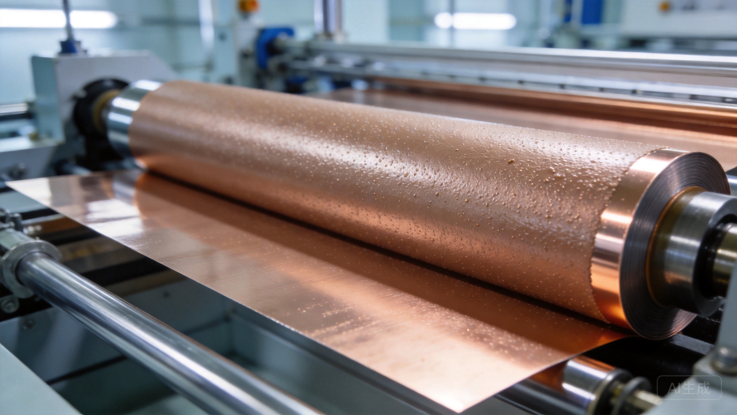
A Complete Additive Landscape for Waterborne Battery Binder Systems
There is a frequently overlooked rule in the manufacturing of lithium-ion battery anode electrodes: the process steps that determine electrode quality—mixing, dispersion, coating, drying—almost all take place before the binder “officially appears”. Waterborne binders such as CMC and SBR are responsible for the final task of bonding active material and conductive agent particles together and anchoring them to the current collector. But before these binders are introduced, whether the slurry is uniformly dispersed, whether particles remain stably suspended, whether interfaces are adequately wetted, and whether air bubbles have been removed, has already determined the fate of the electrode in terms of powder shedding, cracking, and localized high resistance. This article organizes this “complete additive landscape” into a reference map: what problem each additive category solves, where it is added in the process sequence, and what verification criteria apply—while clearly indicating which content comes from internal company experiments and which still requires individual validation against customer formulations.
1. Why a “Complete Landscape”? The Binder Is the Last Piece of the Puzzle
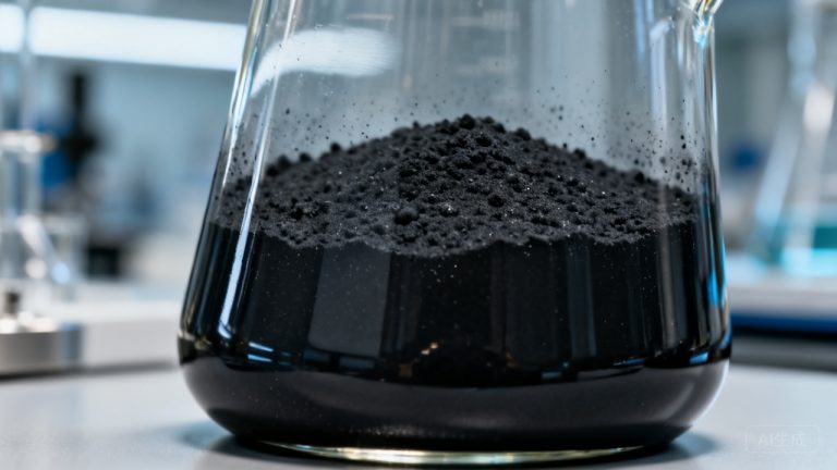
A typical waterborne anode slurry contains active material (graphite/hard carbon), conductive agent (conductive carbon black/carbon nanotubes), a waterborne binder system (mainly CMC + SBR), small amounts of process additives, and deionized water. Simplified into a reference framework, the approximate composition is: active material 90–95%, conductive agent 1–5%, binder system 2–6%, ammonia water 0–2%, with the remainder comprising dispersion/stabilization/wetting/defoaming additives and deionized water (resistivity generally not lower than 1 MΩ·cm).
What is most easily underestimated in this formulation is the fraction of additives ranging from a few tenths of a percent to a few percent. Their quantities are small, but their role is significant: dispersants determine whether the conductive agent and active particles are uniformly distributed; suspension stabilizers determine whether the slurry settles or stratifies upon standing; wetting agents determine whether the slurry spreads uniformly on copper foil; defoamers determine whether residual bubble voids remain in the electrode after coating. If any one of these links fails, the problem ultimately manifests as electrode defects—which is why issues like “powder shedding” often require examining the entire process chain rather than only the binder.
2. Five Categories of Functional Additives for Anode Slurries
2.1 Dispersants: Solving “Particle Agglomeration” First
Conductive carbon black and graphite particles have large specific surface areas and high surface energy, making them highly prone to agglomeration in water. Dispersants break up agglomerates and maintain stable dispersion by forming an adsorption layer and charge repulsion on particle surfaces. This is the foundation of slurry uniformity—if dispersion is poor, all subsequent indicators are meaningless.
For Toynol® products with clearly documented parameters in this category: ET-204 and ET-205 (amine-alkyl-hydroxy adducts of styrene-maleic anhydride copolymer), both waterborne, APEO-free, with a published electrochemical window of 0.1V–4.8V (vs. Li/Li⁺). According to product documentation, ET-204 has 30% non-volatile content and ET-205 has 40%; for conductive agent dispersion, add at 15%–50% of conductive agent mass (ET-205) or 15%–30% (ET-204); for anode active material, add at 0.5%–3.0% of active material mass; packaging 25/200 kg, shelf life 24 months. DS-172 is a dedicated grinding dispersant for conductive carbon black, published as compatible with PVDF and CMC, APEO-free, with the addition sequence being “add to the grinding base first, mix, then introduce conductive carbon black”, at a dosage of 60%–160% of carbon black mass (as-supplied basis), storage 5–40°C, shelf life 24 months.
Parameter sources: Toynol® product documentation (Evidence Level A/B). Values such as “0.5%–3.0% for anode active material” and “15%–30% for conductive agent” are published recommended application ranges and must be verified against the customer’s specific formulation.
2.2 Suspension Stabilizers: Maintaining “Non-Settling” of the Slurry
Dispersion addresses whether particles can be separated; stabilization addresses whether they remain separated over time. Suspension stabilizers significantly slow particle settling through thickening or steric hindrance, keeping the slurry uniform during storage, transport, and pumping. The representative candidate in this category is AN-12 (suitable for pH 7–10), with a reference range of 0.05%–0.2% in anode slurries per internal compilation notes—this range is an Evidence Level C/D development screening suggestion and requires system-specific verification.
2.3 Wetting Agents: Ensuring the Slurry “Spreads” on Copper Foil
At the moment the slurry leaves the coating head onto copper foil, if the slurry surface tension is higher than the copper foil surface energy, it retracts and forms droplets, resulting in exposed foil or uneven thickness. Wetting agents address this interfacial problem. For anode slurry applications, FS-640 (acetylenediol polyether nonionic, static 33.7 / dynamic 35.1 dyn/cm, measured in 0.1% aqueous solution at 25°C) can be evaluated based on published documentation describing suitability for high-speed coating in waterborne systems. The internal compilation notes give a reference dosage of 0.1%–0.5% (Evidence Level C/D, requires verification).
2.4 Defoamers: Eliminating Bubbles That Become “Voids”
Mixing and high-speed dispersion inevitably introduce air. If bubbles in the slurry are not removed before drying, they leave voids in the electrode after drying, appearing as localized looseness, higher resistance, and susceptibility to powder shedding. The reference from internal compilation notes is Foamic-021 (0.1%–0.3%, waterborne molecular defoamer, silicone-oil-free, mineral-oil-free, APEO-free).
2.5 Process Additives: The Timing of Ammonia Addition Is a Critical Rule
Alkaline waterborne slurries commonly use ammonia water to adjust pH and assist dispersion. Internal company experiments (experiment records; conditions detailed in Section 5) confirmed that ammonia water must be added after grinding is complete. If added before grinding, particle size increases significantly after 50°C/24 h thermal storage (exceeding 50 μm in the experiments) with a marked viscosity rise, indicating system instability. This process rule should be communicated clearly in technical discussions with customers.
3. Reference Formulation Framework and Process Sequence
Table 3-1 Reference formulation framework for waterborne anode slurry (compilation notes, Evidence Level C/D)
| Component | Reference ratio/dosage | Function | Evidence level |
|---|---|---|---|
| Hard carbon/graphite (anode active material) | 90–95% | Active material | Compilation reference |
| Conductive agent (conductive carbon black/CNT) | 1–5% | Conductive network | Compilation reference |
| Dispersant (ET-204 / ET-205 / DS-172) | 0.5–3.0% solids; 60–160% of carbon black mass for conductive agent dispersion | Particle deagglomeration and stabilization | A/B (product documentation) + compilation notes |
| Suspension stabilizer (AN-12) | 0.05–0.2% | Prevents settling/stratification | C/D development screening |
| Wetting agent (FS-640) | 0.1–0.5% | Spreading on copper foil interface | C/D (parameters A-grade) |
| Defoamer (Foamic-021) | 0.1–0.3% | Bubble removal | C/D (parameters A-grade) |
| CMC + SBR binder system | 2–6% | Bonding and anchoring | Compilation reference |
| Ammonia water (25% grade) | 0–2% | pH adjustment / dispersion aid | Compilation reference |
| Deionized water | Balance | Dispersion medium | Compilation reference (resistivity ≥1 MΩ·cm) |
Formulation framework source: internal compilation notes (Lithium Battery Hard Carbon Anode Slurry Additive Competitive Analysis Report, compiled by Zhou Quan), Evidence Level C/D reference; not a production formulation commitment; all ratios must be verified on the customer’s actual system.
Table 3-2 Recommended process sequence (compilation notes)
| Step | Action | Key points |
|---|---|---|
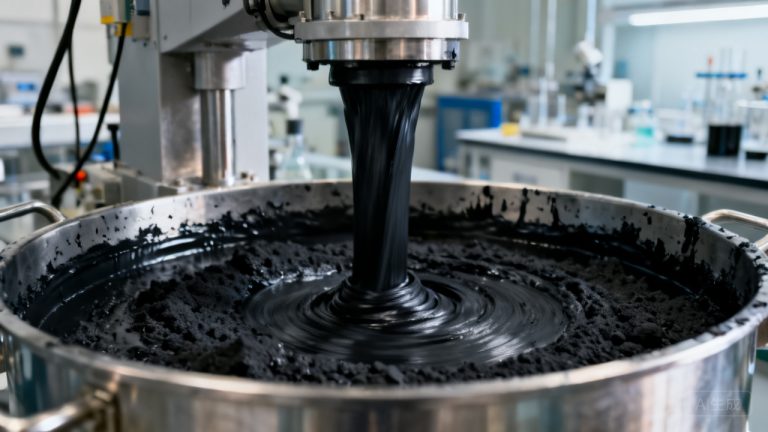
| 1 Dissolution | Deionized water → dispersant → wetting agent → defoamer, dissolve uniformly at 500–1000 rpm | Additives enter the liquid phase before solid materials for optimal spreading |
| 2 Premixing | Add conductive agent and premix | For DS-172 applications, follow “add to grinding base first, then carbon black” |
| 3 Grinding/dispersion | Add active material, sand mill 1–2 h, target D98 ≤ 20 μm | Grinding stage is critical for bubble generation and particle size control |
| 4 Stabilization | Add AN-12 suspension stabilizer after grinding is complete | Stabilizer should not enter the grinding/shear stage prematurely |
| 5 Binder addition | Add CMC + SBR system | Binder should be added after dispersion is complete to avoid shear damage to its network |
| 6 Deaeration | Vacuum deaeration (or settling) | Remove bubbles before drying to prevent electrode voids |
Process sequence source: internal compilation notes (Evidence Level C/D). “Ammonia water must be added after grinding” is an internal experimental conclusion (see Section 5); “binder added last, vacuum deaeration” is industry common knowledge and a compilation suggestion requiring production-line verification.
4. Verification Criteria at the Lab-Scale Stage
Regardless of formulation adjustments, it is recommended that all evaluations be conducted against the same set of criteria to facilitate horizontal comparison and record-keeping:
Table 4-1 Lab-scale verification criteria (compilation notes)
| Indicator | Reference criterion | Notes |
|---|---|---|
| Slurry viscosity | 2000–8000 cP @25°C / 10 s⁻¹ | Excessively high affects pumping and coating; excessively low causes settling |
| Fineness D98 | ≤ 20 μm | Particle size criterion for grinding adequacy (grindometer or particle size analyzer) |
| Thermal storage stability | 50°C / 24 h without hard sediment; solids content difference between top and bottom layers ≤ 5% | Simulates transport and tank residence |
| 180° peel strength | ≥ 0.5 N/cm | Common criterion for electrode–current collector anchoring strength |
| Electrolyte immersion | EC/DMC = 1:1 + 1 M LiPF₆ immersion for 48 h, no blistering, delamination, or significant discoloration | Simulates electrode integrity after electrolyte wetting |
Indicator and criterion sources: internal compilation notes (Evidence Level C/D). Criteria are reference values; final acceptance is governed by customer and battery manufacturer standards.
5. Insights from Two Sets of Internal Experiments (Condition-Limited Citation)
The following content comes from internal company experiment records. Conclusions are valid only under the systems and conditions described in the original reports and must not be generalized to other formulations. Without parallel data under identical conditions, findings will not be characterized as “superior to / replacement for / best”.
5.1 Dispersant Comparison in a Graphite System (Experiment dated 2023.12.6)
Experimental conditions: 10% graphite slurry, 8 dispersants each at 4% addition (SOP), FS-640 0.3%, Foamic-021 0.3%, 25% ammonia water 5%, grinding at 3000 rpm for 1 h, grindometer evaluation, 50°C/24 h thermal storage. Results: ADS-20 achieved the <10 μm range with the lowest viscosity and excellent filtration, making it the preferred choice under these conditions; DS-198 achieved <10 μm at a low dosage of 0.58%, making it the most economical option under these conditions; DS-162A, DS-192M, BNO-12, and SN-5027 were acceptable under these conditions with moderate viscosity; DS-195L was unacceptable at >30 μm under these conditions; LFS-210 generated excessive foam and was difficult to filter under these conditions, making it unacceptable.
Source: internal experiment record (2023.12.6, graphite system). Conclusions apply only to the “10% graphite, 4% dispersant dosage” condition set; dosage screening must be repeated for any formulation change.
5.2 Dispersant Comparison in an Aluminum Foil Slurry (Experiment dated 2023.09.15)
Experimental conditions: alumina/CMC/SBR aluminum foil slurry, 10 μm wire-bar coating; dispersants at two dosage levels of 3% and 6% of powder addition, using both pre-addition and post-addition methods. Results: DS-195L showed significant improvement with 3% post-addition under these conditions, with 6% pre-addition being optimal under these conditions; ADS-20 showed slight improvement at 3% but deteriorated at 6% under these conditions; DS-192M and DS-1702 showed improvement at 3% and were usable under these conditions. This experiment set achieved fineness <5 μm; conclusions require production-line verification.
Source: internal experiment record (2023.09.15, aluminum foil system). The comparison across the two experiment sets is particularly important: the same dispersant (DS-195L) was unacceptable in the graphite system but optimal in the aluminum foil system—directly demonstrating that “product selection must be based on lab trials using the actual formulation”, and cross-system conclusions cannot be applied directly.
5.3 Ammonia Addition Timing—A Critical Rule (Internal Experiment)
See Section 2.5: adding ammonia before grinding causes particle size to increase significantly after 50°C/24 h thermal storage (greater than 50 μm in this experiment set) with noticeable thickening. Ammonia must be added after grinding is completed.
6. Separator Ceramic Coating and Cathode Directions: Honest Boundaries
Beyond anode slurries, the company’s additives have two additional application areas in battery materials. These are described here to maintain clear information boundaries:
6.1 Separator Ceramic Coating
The official website’s “New Energy—Battery Materials Additives” section already covers additive solutions for separator ceramic coating. Published application references for this direction: PE separator coating speed approximately 150 m/min, with film mottling observed at speed ratio ≥1.0; slurry solids content 33–37%; ceramic powder D50 0.3–0.8 μm, D99 1.0–3.0 μm; coating slurry viscosity 200–250 CPS (25°C/61#/12RPM). It is particularly important to note: the core criteria for separator coating additive selection are particle size distribution, viscosity window, and speed ratio matching. “APEO-free” is merely an environmental constraint, not a sufficient condition for “suitable for battery separators”—such statements should not appear in external communications.
6.2 Cathode Direction and Binder Itself: Clearly Flagging Gaps
Boundaries that must be honestly communicated to customers: First, no dedicated dispersion products have been filed for cathode active materials (e.g., lithium iron phosphate, NCM precursors); related requirements are handled as [pending internal confirmation] without fabricating product models. Second, the official website’s battery materials section currently has no product entries for waterborne binders (CMC/SBR/PVDF waterborne)—the binder itself is not within the company’s product scope; this article covers the dispersion, stabilization, wetting, and defoaming additives surrounding the binder system. Third, Vanconol® HCI-1201 is an acidic pickling corrosion inhibitor (alkyl imidazoline derivative blend); it is not applicable in alkaline waterborne anode systems and must not be used in corrosion-inhibition descriptions for anode slurries.
7. Consultations and Samples
If you require a screening trial of additive gradients for your anode formulation, or wish to request samples and TDS for products such as ET-204 / ET-205 / DS-172 / FS-640 / Foamic-021 / AN-12, please contact us through the following channels. The company laboratory can conduct dispersion, thermal storage, and coating lab trials on your slurry system before providing an on-site verification plan.
- Company: Tianjin Hi-Perferal Advanced Materials Co., Ltd.
- Address: No.2-1, Zhengshuaidao, Caozili, Wuqing District, Tianjin, China
- Technical service hotline: 022-82910362
- Official website: www.surfychem.com
Services provided: free samples, slurry lab-scale formulation design, laboratory coating and thermal storage testing, and on-site process guidance.